

Gravity and pump-fed tank dewatering are not interchangeable calculations. In a gravity installation, the liquid level provides the driving head. A pump can change pressure, flow and shutoff conditions, so the valve and complete route need a more detailed review.
Belfield literature acknowledges gravity and pumped applications, while also directing certain higher head and pressure cases to individual assessment. This guide lists the information to collect without prescribing a pump arrangement.
What changes when a tank dewatering duty is pumped
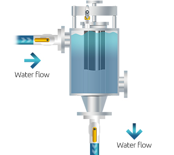
Describe the source of pressure
For a gravity drain, state the tank level above the valve and how that level changes during the cycle. Include the minimum level at which drainage is expected to continue, not only the normal starting level.
For a pumped arrangement, identify the pump model, curve, operating point, maximum or shutoff pressure and control method. Explain whether the pump is upstream or downstream of the valve and what the system does at startup, stop and blocked discharge.
A pump can make the available pressure different from the simple liquid head in the tank. The application engineer needs the hydraulic boundary and the pump response rather than a statement that the system is just pumped.
For a variable speed pump, provide the programmed speed range and any pressure control set points, including ramping. Show whether a bypass can return flow to the tank or divert it elsewhere; these details can change the pressure seen by the valve during a drain.
Include the whole piping arrangement
Provide a current P&ID or dimensioned sketch that shows tank nozzles, valve orientation, inlet and outlet sizes, isolation valves, check valves, vents, bypasses, reducers and pipe elevations. Identify every component between the tank and receiving destination.
Belfield gravity installation guidance calls for vertical mounting close to the vessel, a full-size inlet, a full bore outlet valve and a short, straight downstream run. A pumped design needs review against the same current product instructions plus the additional pump and pressure conditions.
Identify restrictions introduced by control or check valves and note whether they are normally open, closed or modulated. Do not remove or bypass an installed safeguard to improve a test result.
Check pressure and head against published guidance
Published capacity is based on a reference head and changes with the liquid properties and system. The Belfield performance page notes that higher head applications depend on pressure, temperature and discharge arrangement and should be referred for individual calculation.
A nominal capacity table cannot tell you what a pump will deliver through a particular valve and pipe route. The correct operating point depends on the pump curve and system resistance, including the receiving conditions downstream.
Provide minimum, normal and maximum tank level, process pressure and downstream pressure. If these are not known, ask the site engineering team how to obtain them safely rather than substituting an assumed design value.
Explain what phase is expected at each boundary
State which phase should pass through the main outlet and where the other phase will remain or be recovered. Include the expected interface behaviour, any intermediate layer and the point at which the pump starts or stops relative to tank drainage.
The valve responds to a change in the liquid at its mechanism when the phases and duty are suitable. It does not make a pump safe to run dry, control every upstream process condition or prove that the downstream liquid meets a discharge limit.
Describe the action when the valve closes or the receiving route is unavailable. That sequence must be developed with the responsible process and safety engineers and reflected in approved control and operating documents.
Review abnormal and transient conditions
Include a closed discharge, pump startup, pump trip, loss of power, low tank level and a partially blocked line where those cases are credible. The pump may produce a different pressure at these conditions than during a steady drain.
Explain how relief, isolation and containment are handled under the approved design. This article does not size safety devices or recommend changing a valve sequence. Those decisions need an engineering review of the full pressure boundary.
If the liquid is hot, viscous, contains solids or has a close density difference, list those conditions alongside the hydraulic data. A pump does not remove the need to check liquid compatibility or phase separation.
- Pump curve, model, control and shutoff information
- Minimum, normal and maximum tank level and head
- Pressure upstream and downstream of the valve
- Current P&ID and all line restrictions
- Liquid pair, temperature, viscosity and solids
- Expected response to a closed or unavailable outlet
Request a review before changing a running system
Changing a gravity system to a pump, or adding a pump to an existing valve, can alter the design basis. Use the site management of change process and confirm the valve model and pressure limits before the modification is approved.
The enquiry should identify the required duty, operating envelope, proposed pump and complete pipe route. A manufacturer can then confirm whether the specific arrangement is within the product guidance or needs further calculation or testing.
Keep the decision with the approved drawings, pump data and operating procedure. Revisit it when the pump, product, tank level or receiving conditions change.
The question is not simply whether a pump can push liquid through the body. The review needs to establish the expected operating point, the response at the phase interface and the safe outcome when the flow path changes. A complete drawing and pump curve are more useful than a requested flow rate on its own. Include the operating philosophy for normal cycling and abnormal stop conditions so the selection and control design are considered together.
Frequently asked questions
Can a Belfield Valve be used with a pump?
Pumped arrangements may be considered, but the specific pump, head, pressure, liquid properties and pipework must be reviewed. Do not assume a gravity selection transfers unchanged.
Can I use nominal capacity to choose the pump?
No. Nominal valve capacity is a reference value. The pump and system curve, liquid properties and complete downstream route determine the actual duty.
What pump information should be sent?
Include the pump model and curve, operating and shutoff conditions, control method, pressure data and the location of the pump relative to the valve.
Does the valve replace downstream protection?
No. Isolation, containment, pressure protection, treatment and site operating procedures remain separate design responsibilities.
Sources and further reading
Review the Belfield performance data and installation guidance before preparing the duty.
The sizing and selection page lists pumped systems among the conditions to refer for application review.
Next steps
For a pumped duty, include the pump curve and current P&ID with the process information sent to Belfield support. For more about PMA, visit the PMA website.