


A tank dewatering project does not end at the valve outlet. The receiving route must be able to accept the intended stream, while the site needs a plan for product detection, isolation, containment and treatment if conditions differ from normal.
A Belfield Valve may help control a phase at the discharge point in a suitable duty. It is not a wastewater treatment plant and does not establish that a discharge meets a consent or site limit. This guide focuses on the route after the valve.
How to plan the receiving route for tank dewatering
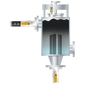
Define what stream the outlet is expected to receive
State which phase is intended to pass, what may remain in the vessel and whether a side run-off or separate recovery route is part of the design. Describe the expected range of water quality and any intermediate material rather than labelling everything as clean water.
Identify the receiving equipment by name and drawing: sump, closed drain, wastewater treatment, sampling vessel or another approved destination. Confirm who owns the route and whether it is available during each expected operating state.
A receiving system should be reviewed for its capacity, material compatibility, normal back pressure and the consequences of an unavailable destination. The valve cannot make an undersized or unsuitable downstream route safe.
Keep phase control separate from treatment and compliance
The phase responsive valve can close its main outlet as the lighter phase reaches the float in a suitable application. That action is different from measuring every contaminant, removing dissolved substances or proving an effluent quality limit.
The Belfield effluent page states that the valve is one part of a reviewed system and does not guarantee that discharged water meets a consent limit. Monitoring, treatment and site safeguards remain separate responsibilities.
Use the site environmental permit, discharge consent and operating procedures to determine what sampling, analysis and record keeping are required. This article is not legal advice and cannot determine whether a particular discharge is permitted.
Map isolation, observation and containment points
Mark the tank isolation, valve, sample or observation points, receiving tank or drain, containment boundary and any emergency stop or alarm. Show the normal route and the route used when a component is unavailable.
HSE HSG176 for fixed bulk storage of flammable liquids includes specific precautions for tank drainage, including blanking drainage valves when not in use and not relying on a single valve alone to retain the tank contents during drainage. The guidance has a defined scope and should be applied with the site risk assessment.
For other stored materials or tank arrangements, use the rules and engineering standards that apply to that installation. Do not copy a safeguard from another site without checking the pressure boundary and operating case.
- Tank, valve and receiving equipment boundaries
- Normal and abnormal routes shown on a current drawing
- Sampling or observation point and measurement method
- Isolation and containment responsibilities
- Treatment, disposal and record keeping requirements
Plan for an unexpected phase or a closed route
The process should say what happens if product appears at the receiving point, the valve closes early, the outlet is blocked or the treatment system is unavailable. The response should come from the approved site procedure and match the actual isolation arrangement.
Consider where liquid can accumulate after closure and whether trapped pressure, gravity flow or a pump can continue to move material. These are engineering questions for the project design, not settings to adjust during operation based on a blog post.
Identify who has authority to stop the operation, who receives an alarm and how the site communicates an abnormal event. Verify those steps through the site commissioning and training process.
Check the receiving route as operating conditions change
A change in tank product, drainage rate, temperature, solids or pump operation can change the volume and condition of the receiving stream. A treatment plant that was suitable for one pattern may not be suitable for another.
Review new filters, check valves, pipe length, elevation and receiving vessel level as part of the overall hydraulic design. Back pressure affects flow and may affect the valve duty. The current manufacturer guidance should be consulted for the specific arrangement.
Keep the route drawing current and record inspections, samples, alarms, maintenance and disposal. If the downstream destination or consent changes, revisit the whole discharge assessment before assuming the existing valve arrangement remains adequate.
Document the result without making a blanket claim
A project report can state where water was routed, what monitoring was used and what was observed during a defined period. It should identify the process, sample method, limits and any exception rather than claim zero carry-over or guaranteed compliance without evidence.
Separate valve performance from treatment performance. A successful phase response does not show that dissolved contaminants were removed; a compliant sample does not by itself prove how much product was retained.
If the site wishes to publish an environmental benefit or product recovery figure, obtain evidence from the actual duty and the necessary approvals. State the measurement basis and do not generalise a site-specific result to every installation.
Keep records of who reviewed the route, which drawing revision was accepted and when the consent or treatment basis was last checked. A change in receiving equipment, sampling point or product can make a previous operating description out of date even when the valve itself has not changed. Review the record after a process modification so the operator can find current isolation and escalation information without relying on an old project file.
Frequently asked questions
Does a Belfield Valve certify a wastewater discharge?
No. It is a phase responsive discharge device, not a treatment plant or compliance certificate. Monitoring, treatment and consent obligations remain with the site.
What should the outlet connect to?
The destination must be selected and approved for the actual liquid, flow, pressure, treatment process and site rules. Provide the proposed route for engineering review.
What does HSG176 say about tank drainage?
For fixed bulk storage of flammable liquids, it recommends precautions including blanking tank drainage valves when not in use and avoiding reliance on one valve alone. Confirm applicability to the site.
Can I claim that a valve prevents all oil carry-over?
Do not make an absolute claim without measured evidence. Performance depends on the actual liquid pair, installation and operating conditions.
Sources and further reading
See Effluent Protection and Product Recovery for the distinction between phase control and downstream treatment.
HSE HSG176 covers flammable liquid storage in fixed bulk tanks within its stated scope.
Next steps
Share the receiving route, monitoring point and process conditions with the Belfield application team before treating the valve as the complete discharge solution. For more about PMA, visit the PMA website.