

Oil appearing in a tank drain does not automatically prove that a decantation valve has failed. Carry-over can begin upstream, arise from an unclear interface, or reflect a change in the pipework or liquid pair. A useful investigation follows the full path from tank to receiving point.
This checklist is for process review and record keeping. It does not replace the Belfield operating manual, site procedures or a review of the actual installation. Do not change a setting or open equipment based on a generic article.
Where oil carry-over can enter a tank dewatering cycle
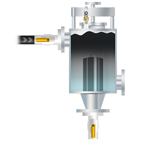
Confirm that the liquids have formed a usable interface
A mechanical decantation valve responds to a change in the liquid reaching its float. It is not a treatment plant that breaks an emulsion or separates a continuously mixed stream. If the tank contains a rag layer, dispersed droplets or unsettled material, the outlet may not see a clear change from one phase to the other.
Record how long the tank was left to settle, what happened immediately before drainage, and whether transfers, mixing, recirculation or filling could have disturbed the contents. A recent change in feedstock, additive, water chemistry or temperature can also change how quickly the phases separate.
Describe what was observed at a safe sampling or monitoring point, including whether the interface was sharp, gradual or obscured. If the phases remain mixed, review the process cause first. A different separation step may be needed before a phase responsive drain can be assessed.
Compare the current installation with its reviewed basis
Collect the valve model, serial or nameplate information, approved drawing and the date of the last application review. Compare the present liquid pair, temperatures, available head, required flow, valve orientation and pipe arrangement with the documented basis. Missing records should be recorded as unknown, not filled with an assumed value.
Belfield product guidance for gravity discharge describes vertical installation close to the vessel, an inlet no smaller than the valve inlet, a full bore outlet valve and short, straight downstream pipework. These are manufacturer instructions to check against the actual model and drawing, not a substitute for inspection or engineering approval.
Note any reducers, control valves, check valves, vents, elevation changes or new downstream equipment. A partial blockage or additional back pressure can affect flow. Do not remove, bypass or reposition a safety or isolation device to test a theory.
- Current valve model and approved drawing revision
- Tank nozzle and inlet sizes, orientation and visible changes
- Downstream valves, restrictions, vents and receiving destination
- Changes to liquid properties, temperature, tank level or procedure
Check whether the operating conditions have changed
The Belfield performance guidance says nominal capacity depends on the liquids, temperature, viscosity, specific gravity and float ballasting. It also treats some higher head, temperature and viscosity duties as requiring individual factory review. A condition that was acceptable at commissioning may no longer describe the process today.
Record minimum, normal and maximum temperature, including a cold start or shutdown condition where relevant. Ask for viscosity at the actual operating temperature rather than relying on a value measured at room temperature. Note solids, wax, sludge or deposits and describe their nature and concentration.
For a pumped or pressurised arrangement, capture the pump information, pressure conditions, check valves and a current piping and instrumentation diagram. The published guidance calls for individual review in specified higher head conditions. Do not extrapolate a gravity selection into a pumped duty.
Make the response to an abnormal outlet clear
The receiving system should have an agreed response when product is detected where only the heavier phase is expected. That response belongs in the site operating procedure and must match the installed isolation and containment arrangement. This article does not prescribe a valve sequence or permit-to-work method.
HSE guidance for flammable liquids in fixed bulk storage says tank drainage valves should be blanked when not in use and drainage operations should not rely on one valve alone to retain tank contents. That guidance has a defined scope; confirm the rules and safeguards that apply to the particular site and stored material.
Record who was notified, what safe containment was used, whether product reached the intended boundary, and what follow up was agreed. If there is a release or immediate hazard, use the site emergency procedure rather than continuing a troubleshooting test.
Measure the result instead of relying on a single observation
A useful investigation compares similar operating cycles. Record the tank level and head, liquid temperature, drain start and stop times, volume or mass removed, method used to identify the outlet phase, and any sample result. Include the sampling point and method so that later measurements can be compared fairly.
Separate direct measurements from estimates and operator observations. A single clear sample does not establish that carry-over has been eliminated, and one affected sample does not identify the cause. State missing data and uncertainty rather than converting them into a performance claim.
If the site makes a change after engineering review, repeat the same measurements over a representative period. Compare residual water, product at the receiving point, time and maintenance events under similar conditions. The measured outcome belongs to that duty and should not be presented as a guarantee for another tank.
Use the findings to decide what needs support
If the liquid pair and operating envelope are unchanged but the symptoms have changed, provide the service team with the chronology, model details, conditions and photographs. If the product or installation has changed, request an application review before adjusting ballast or altering pipework.
The most useful report is concise and factual: what changed, when it changed, what was measured, what was observed and what remains uncertain. A marked up drawing can expose a restriction or route change that is difficult to describe over the phone.
A Belfield Valve can help manage product at the point of discharge in a suitable application. Its role is one part of the tank, isolation, sampling, containment and treatment system. Keep the investigation within those boundaries and preserve a safe record for the next shift.
Frequently asked questions
Does oil at the outlet always mean the Belfield Valve has failed?
No. Settling, an emulsion, a changed liquid pair, temperature, head or pipework can affect what reaches the valve. Capture the duty and receiving point before deciding on a cause.
Can I throttle the outlet to stop carry-over?
Do not improvise a restriction. Review the complete hydraulic arrangement and the current manufacturer instructions with the site engineer or PMA.
What evidence is useful to service support?
Share the valve model and drawing revision, process conditions, timeline, measured observations, photographs and a marked up piping sketch. Identify estimates and missing values.
How can a site show that a change helped?
Use a consistent measurement method over comparable cycles and report residual water, outlet observations, drain time and maintenance events with the limits of the data.
Sources and further reading
Belfield installation and operating guidance and performance data describe the product conditions referred to in this checklist.
HSE HSG176 covers flammable liquids in fixed bulk storage tanks and includes precautions for tank drainage. Its scope is not every liquid storage installation.
Next steps
For application support, send the liquid pair, operating temperatures, viscosity, available head, required flow and a current vessel or piping sketch through the Belfield contact page. For more about PMA, visit the PMA website.